Teletype Model 28 ASR Typing Reperforator (LPR) Consistently Punches Several Wrong Holes
When I got my ASR home and began to learn about operating it, I discovered that it printed well off the loop, but when printing from the keyboard, it often would print 3 or 5 holes consistently with every character regardless of the character being typed. This was somewhat disconcerting since I knew absolutely zero about these machines and doubted I could figure this out. Thanks to several very nice folks from the QTH greenkeys list, I learned quite a bit.
In the model 28, the LPR typing reperforator can be controlled either via the keyboard (using bars that make mechanical connections to the keyboard code bars) or via the loop. When using the keyboard in either KT or T positions, a reset bail (p/n 152410) must lift up and disconnect the push levers (p/n 152411) from the selector magnet. Therefore, the reperf will only take code commands from the keyboard.
In my 28 ASR, this was not occurring. Instead, when perfing from the keyboard after using the loop, I had to manually lift up the reset bail to clear the code bars (push levers). Otherwise, I would have certain bits “stuck.” Most typically I would have all 5 bits stuck such that no matter what character I typed, I would get 5 punched holes. Although sometimes, I might get 3 punched holes and the remaining two holes might actually represent the right hole/no-hole for the character being typed. Thus I began a quest to understand what was not working properly and why.
With tons of help from fellow greenkeyers http://mailman.qth.net/mailman/listinfo/greenkeys I learned that the K/KT/T knob actuated a cam, either p/n 158114 or p/n 176436 hidden inside the metal base frame that holds the reperf. This cam was supposed to operate an “h” shaped slide bar than then pushed up the reset bail. The difference between the two cams is, 158114 will only push up when in the “T” position, 176436 will push up in either the KT or T position.
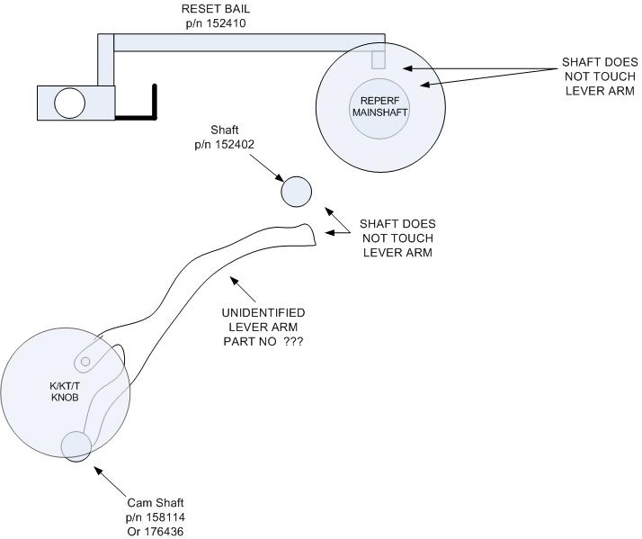
For the life of me, I could not understand how this worked. To begin with, it is very difficult to see into the depths of the reperf, behind and between all kinds of mechanical wonderment. But what I could not figure out is how an “h” shaped, vertically oriented push slide could be actuated by the cam and actuate the reset bail because they were in different planes. This first diagram shows what appeared to be what I had to work with. Note an unidentified lever. At first, I thought this lever might have been the elusive 159880 that might have slipped into the wrong position.
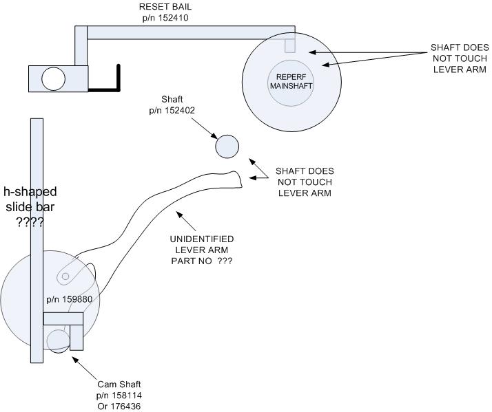
Upon closer inspection, this part simply did not look straight enough to be the part 159880 as depicted in manual 270B, Change 1 page 5-19. So I tried to figure out how the introduction of 159880 could work. In this second diagram, you will see my confusion (which lasted several weeks). I was under the impression that this “h” shaped slide bar was directly operated by the cam from the K/KT/T knob.
The confusion stemmed from this fact. If the “h” shaped slide bar was operated directly from the cam, then it would be directly in line with the pivot of the reset bail, and certainly could not reset it.
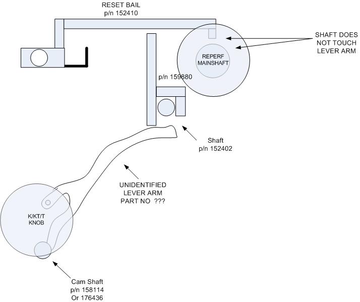
In an effort to figure this all out, I began to draw the first diagram above. It struck me as odd that the little, handle end of the reset bail was oriented directly above the main shaft. I could not figure out how any “h” shaped slide bar could press against the handle based on its location. The unidentified lever (which until this point I had completely discounted) was positioned, not under the handle end of the reset bail, but surely under the center span of the arm of the reset bail. Another comparison to the diagram (manual 270B, change 1, page 5-15 [figure 5-18]) showed something I did not see before. This figure depicted the “h” shaped slide interfacing to shaft 152402, not any cam near the K/KT/T knob. Then came the epiphany. The elusive “h” shaped slide bar would sit on this shaft which is located precisely between the unidentified lever and the center span of the reset bail arm! To see the final concept,see next diagram below. This was the final piece to the puzzle. I know understood how the K/KT/T knob could actuate the reset bail
One more note. As mentioned above, the cam does not actuate 159880 (“h” shaped slide bar”) but actuates the unidentified lever. Also noted above was that there were two possible cams, 176436 and 158114. What is the difference and how can you determine which you have? Carefully shine a flashlight to view the behavior of the unidentified lever (see diagram one). Place the K/KT/T knob in the K position. This lever should be at a low point of travel. If placing the K/KT/T knob in KT moves the lever up, then you have cam 176436. If it does not move the lever up in the KT position, proceed to rotate the knob to the T position. At this point the lever should raise. If this is the case (lever only raised in the T position) then you have cam 158114.
What is the difference? With the 158114 cam, the reperf will stay connected to the selector magnets in the K and KT position. This is not desirable if you run your reperf off the loop and then want to punch tape and print on the printer from the keyboard. By going from loop to KT your reperf will be controlled by both the loop and the keyboard. This can cause the condition explained above with the constant set of holes being punched. This cam requires that the operator be in T position to reset the bail and therefore be able to go from loop to keyboard operation of the reperf without issue. Although I do not have this cam, I would imagine one could simply select T first, then KT and the bail will be properly reset.
With cam 176436, the reperf will disconnect from the selector magnets in either the KT or T positions. This sounds much more user friendly to operate. Luckily, I have this cam.
So! If you ever locate a 28 ASR and the reperf likes to punch holes regardless of the character being typed, suspect the reset bail is not resetting. Then check for the presence of the “h” shaped slide bar and from these diagrams you can see where it should be located.